


- tel070-7510-4840
- fax02-6280-8599
- time오전10시~오후6시


[P0000BCX] Arduino M0 
() 해외배송 가능
| 판매가 | |
|---|---|
| 소비자가 | 0원 |
| 적립금 |
|
| 무이자할부 | |
| 제조사 | |
| 원산지 | |
| 상품코드 | P0000BCX |
| 수량 |
|
| 국내/해외배송 | |
| SNS 상품홍보 | |
| QR코드 |
|
| QR코드 보내기 |
   
|


event
상품상세정보

 |
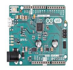
OverviewWith the new Arduino M0 board, the more creative individual will have the potential to create one’s most imaginative and new ideas for IoT devices, wearable technologies, high tech automation, wild robotics and other not yet thinkable adventures in the world of makers. Summary
Schematic & Reference DesignPowerThe Arduino M0 can be powered via the micro USB connection or with an external power supply. The power source is selected automatically. External (non-USB) power can come either from an AC-to-DC adapter (wall-wart) or battery. The adapter can be connected to the board by plugging a 2.1mm center-positive plug into the board's power jack. Leads from a battery can be inserted in the Gnd and Vin pin headers of the POWER connector.
The board will automatically detect which power sources are available and choose which one to use according to the following priority:
External power is required when the 500mA through the USB connector is not enough to power a connected USB device in a USB host application.
The power pins are as follows:
MemoryThe ATSAMD21G18 has 256 KB of flash program memory (with 4 KB used for the bootloader). The bootloader is factory pre burnt by Atmel and is stored in a dedicated ROM memory. The bootloader is protected using the NVM fuse. It also carries 32 KB of SRAM and up to 16KB by emulation of EEPROM (which can be read and written with the EEPROM library). Input and Output
Each of the 14 digital i/o pins on the M0 can be used as an input or output, using pinMode(), digitalWrite(), and digitalRead() functions. They operate at 3.3 volts. 7mA as maximum DC current for I/O pins and an internal pull-up resistor (disconnected by default) of 20-60 kOhms. In addition, some pins have specialized functions:
CommunicationThe Arduino M0 has a number of facilities for communicating with a computer, with another Arduino or other microcontrollers, and with different devices like phones, tablets, cameras and so on. The SAMD21 provides one hardware UART and three hardware USARTs for 3.3V serial communication. The Arduino software includes a serial monitor allowing simple textual data to be sent to and from the board. The RX and TX LEDs on the board will flash when data is being transmitted via the ATSAMD21G18 chip and USB connection to the computer (but not for serial communication on pins 0 and 1). The Native USB port is connected to the SAMD21. It allows for serial (CDC) communication over USB. This provides a serial connection to the Serial Monitor or other applications on your computer. The SAMD21 also supports TWI and SPI communication. The Arduino software includes a Wire library to simplify use of the TWI bus. For SPI communication, you can use the SPI library. ProgrammingThe Arduino M0 can be programmed with the Arduino software (download). Uploading sketches to the SAMD21 is different from how it works with the AVR microcontrollers found in other Arduino boards: the flash memory needs to be erased before being re-programmed. Upload operation is managed by a dedicated ROM area on the SAMD21. USB port: To use this port, select "Arduino M0 (Native USB Port)" as your board in the Arduino IDE. The Native USB port is connected directly to the SAMD21. Connect the M0 Native USB port (the one closest to the reset button) to your computer. Opening and closing the Native port at 1200bps triggers a 'soft erase' procedure: the flash memory is erased and the board is restarted with the boot loader. Opening and closing the native port at a different baudrate will not reset the SAMD21. USB Overcurrent ProtectionThe M0 has a resettable polyfuse that protects your computer's USB ports from shorts and overcurrent. Although most computers provide their own internal protection, the fuse provides an extra layer of protection. If more than 500 mA flows through to the USB port, the fuse will automatically break the connection until the short or overload is removed. Physical CharacteristicsThe maximum length and width of the M0 PCB are 2.7 and 2.1 inches respectively, with the USB connector and power jack extending beyond the former dimension. Four screw holes allow the board to be attached to a surface or case. Note that the distance between digital pins 7 and 8 is 160 mil (0.16"), not an even multiple of the 100 mil spacing of the other pins. |
상품결제정보
* 세금계산서 발행방법은 게시판 공지사항 참조.
* 기술문의는 이메일(master@deviceshop.net)로만 문의 가능.
전자부품 특성상 제품에 이상이 있거나, 상품정보와 상이한 경우 외 에 단순 고객변심으로는
교환 반품이 불가능 합니다 구매전 이점 유의해 주세요!!!
고액결제의 경우 안전을 위해 카드사에서 확인전화를 드릴 수도 있습니다. 확인과정에서 도난 카드의 사용이나 타인 명의의 주문등 정상적인 주문이 아니라고 판단될 경우 임의로 주문을 보류 또는 취소할 수 있습니다.
무통장 입금은 상품 구매 대금은 PC뱅킹, 인터넷뱅킹, 텔레뱅킹 혹은 가까운 은행에서 직접 입금하시면 됩니다.
주문시 입력한 입금자명과 실제입금자의 성명이 반드시 일치하여야 하며, 7일 이내로 입금을 하셔야 하며 입금되지 않은 주문은 자동취소 됩니다.
배송 정보
- 배송 방법 : 택배
- 배송 지역 : 전국지역
- 배송 비용 : 3,000원
- 배송 기간 : 1일 ~ 3일
- 배송 안내 : 산간벽지나 도서지방은 별도의 추가금액을 지불하셔야 하는 경우가 있습니다.
주문하신 제품은 입금확인후 1~3일 내에 출고되며 (해외배송)으로 표시된 제품은
해외배송 제품으로 배송기간이 약 10일~14일정도 소요될수 있습니다.
구매전 해외배송 제품은 배송기간을 꼭 확인해 주세요.
교환 및 반품 정보
교환 및 반품이 가능한 경우
- 상품을 공급 받으신 날로부터 7일이내 단, 가전제품의
경우 포장을 개봉하였거나 포장이 훼손되어 상품가치가 상실된 경우에는 교환/반품이 불가능합니다.
- 공급받으신 상품 및 용역의 내용이 표시.광고 내용과
다르거나 다르게 이행된 경우에는 공급받은 날로부터 3월이내, 그사실을 알게 된 날로부터 30일이내
교환 및 반품이 불가능한 경우
- 고객님의 책임 있는 사유로 상품등이 멸실 또는 훼손된 경우. 단, 상품의 내용을 확인하기 위하여
포장 등을 훼손한 경우는 제외
- 포장을 개봉하였거나 포장이 훼손되어 상품가치가 상실된 경우
(예 : 가전제품, 식품, 음반 등, 단 액정화면이 부착된 노트북, LCD모니터, 디지털 카메라 등의 불량화소에
따른 반품/교환은 제조사 기준에 따릅니다.)
- 고객님의 사용 또는 일부 소비에 의하여 상품의 가치가 현저히 감소한 경우 단, 화장품등의 경우 시용제품을
제공한 경우에 한 합니다.
- 시간의 경과에 의하여 재판매가 곤란할 정도로 상품등의 가치가 현저히 감소한 경우
- 복제가 가능한 상품등의 포장을 훼손한 경우
(자세한 내용은 고객만족센터 1:1 E-MAIL상담을 이용해 주시기 바랍니다.)
※ 고객님의 마음이 바뀌어 교환, 반품을 하실 경우 상품반송 비용은 고객님께서 부담하셔야 합니다.
(색상 교환, 사이즈 교환 등 포함)
AS 지원 안내
(1) 디바이스샵 : master@deviceshop.net
(2) 무상 수리 및 제품 하자 시 교환은 구입 후 7일 이내 이며, 사용자 과실로 인하여 하자가
발생 하였을 경우에는 수리비가 청구 될 수 있으며, AS가 가능한 기간은 3개월이며 사용자 과실로
인한 제품고장시 수리비가 청구됩니다.
서비스 문의

상품 Q&A
상품에 대해 궁금한 점을 해결해 드립니다.
게시물이 없습니다


법인명(상호): 주식회사 제이케이이엠씨 21330 대표자(성명): 김경연 사업자 등록번호 안내: [406-87-00271] 통신판매업 신고 제2022-인천부평-0500호
전화: 070-7510-4840 팩스: 02-6280-8599 주소: 인천광역시 부평구 주부토로 236 (갈산동) 인천테크노벨리U1센터 B동 908
개인정보관리책임자: 김경연(master@deviceshop.net)
Contact jk@deviceshop.net for more information.
Copyright © 2010 Deviceshop All rights reserved.